I rented a pickup trick to haul it home. We took the head and table off and laid the mill on its back. I have an I beam arm bolted to the side of my shop, and a double door arranged for easy acces of big items. I took the mill almost entirely apart before lifting the pieces into the shop. I could have moved it without total disassembly, but I wanted to give it a thourough cleaning and check over as I put it together. I forgot to take any photos of it until it was in the shop and partly reassembled.
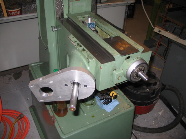
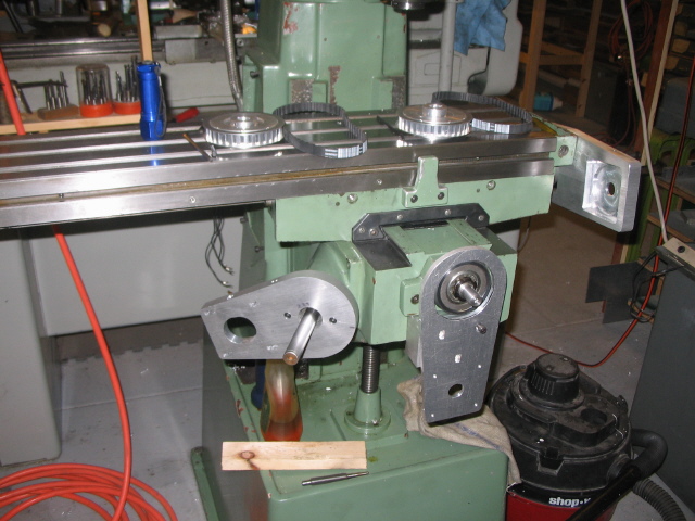
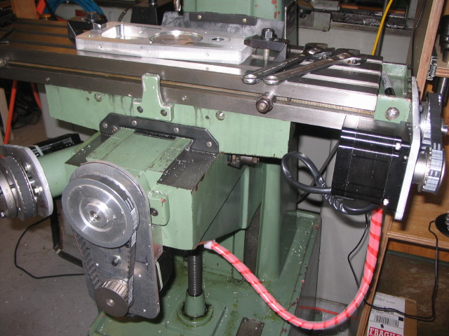
This photo shows the bracket to hold the Z motor- its a simple 3/4" plate of aluminum, milled and drilled to hold the motor. Note Ive attached it to the mill with the 2 screws used to hold on the graduated collar in the origianl machine.
I did not change the knee elevating screw. Its a large acme thread, with a pair of spiral bevel gears driving it. There is considerable backlash in the gears, but I expect the table weight will keep it down, and almost all Z operation I do are simple plunge the tool, or dill, and retract. If it turns out to be a problem I can always add a ballscrew to the quill and just use the knee as a power feed.
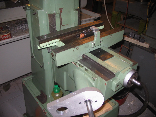
This photo also shows the Y lead screw in place, you can see the aluminum post sticking up that will go into the saddle casting.
The ball nut diameter is limited by the top of the Knee elevating screw. There is plenty of room above it.
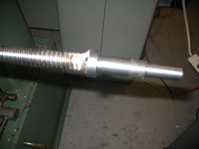
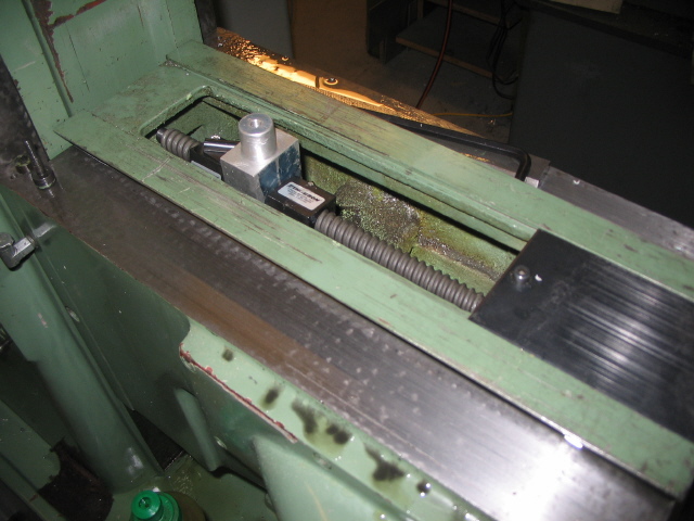
For the back end of the Y screw I turned a short stub to the inside diameter of the keeper that came with the ballnut. This kept the keeper in line as the screw was turned into the nut. I was worried about this operation because it had to be done reaching up under the knee, a very tight and awkard place to reach. I got it in without a problem.
On the X screw I machined the end to the inside diameter of the keeper tube, then made a bushing to fit over that to the inside dimension of the end bearing. There is no shoulder on this end, the bearing simply keeps the screw in alignment, it can float a bit with temperature change.

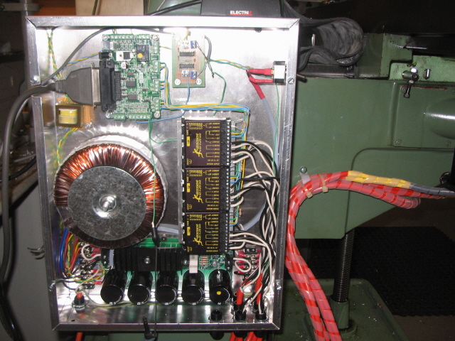
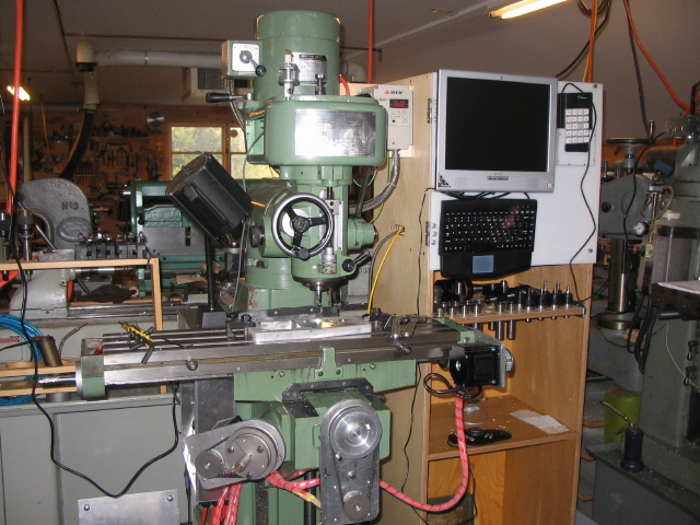
You can see the Geckodrive G320 servo driver modules, and the PMDX breakout board.
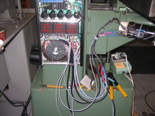
The wires from the servos are being connected to the box in this photo. About this time I realized the box was a bit to small, as things were starting to get crowded.
I got everything together, ready to run just an hour or two before I was to leave for a Thanksgiving trip. I fired up the box, hoping for an instant success, but no such luck. In fact, it appeared I had blown the servo drives, because they a were showing the fault led, and the motors had zero resistance to movement by hand. I was hooking a jumper wire to the breakout board for my scope ground, and I hit something and blew a capacitor on the breakout board- a nice firecracker sound!
At that point I threw in the towel and left for Thanksgiving.
When I returned I got to work checking carefully. I first discovered the G320s were fine- I had simply turned the limit pot all the way DOWN, instead of all the way UP. So any movement immediaetly triggered an over current fault. Dumb, and I had orderd replacement G320s while I was away so they would be on hand when I returned. Fortunately Gecko accepted them for return since I had not used them.
Once I got everything setup the machine ran great. I could move the X and Y axis at 130 in/min with no trouble. Even the Z would move -up and down the whole table- at 130 in/min. I purposely de-tuned that to about 65 in/min because it just seemed to fast.
After about a week of good luck things took a turn for the worse. My servo motors were found in a surplus place, and they had integral brakes. The brakes require 90 volts to keep them released. I wired the power box with two switches, so I could first turn on the brake supply, then turn on the servos. One afternoon I left the machine with the brakes on, but servos off. The next morning when I turned the machine on to continue testing I soon had the smell of burning motor- The Z axis motor brake had locked up, and the servo drive was trying very hard to drive the motor. The motor was VERY hot, the G320 was on a big heat sink, so it was just warm.
I considered buying a new servo. I could not find anything appropriate for under $200. I was also a bit put off by the Geckos- I was never able to tune them to stop the growl when at idle. Apparently that is a "feature" of the Geckos that comes with their low cost. I considered buying just one new stepper for Z and keeping the servos on X and Y, but then Id have a power supply problem- I was running the servos at 80 volts, the stepper would need only about 50v.
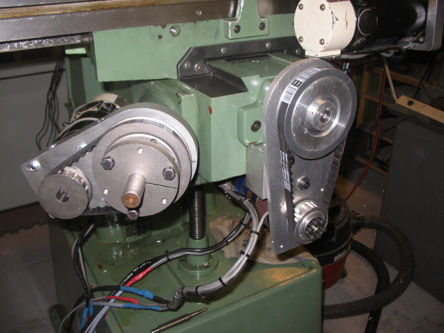
About this time Marris, of Geckodrive, wrote one of his frequent messages about the selection of steppers vs servos. He pointed out that a servo ought to be geared to run at a reasonable speed- for my mill it would work out to about a 5:1 ratio. My pulleys were only 2:1, which is good for steppers.
I finally decided to change all 3 motors over to steppers. I was able to sell the Geckos and the transformer so my net loss was only about $50. I bought 2 740 oz-in and one 1200 oz-in steppers from Home Shop CNC
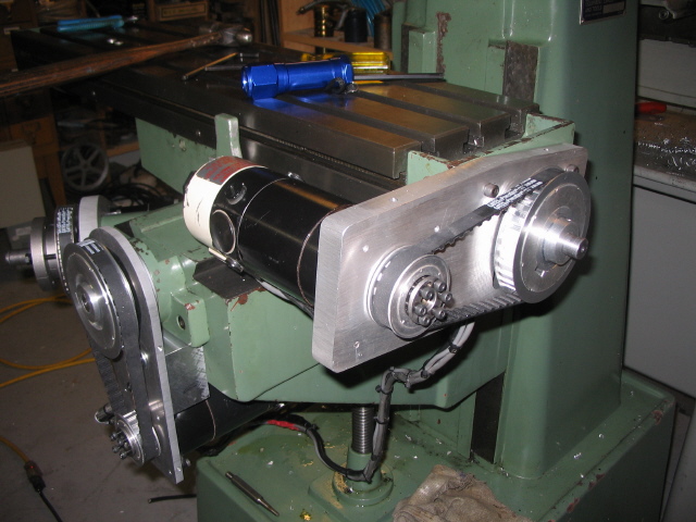
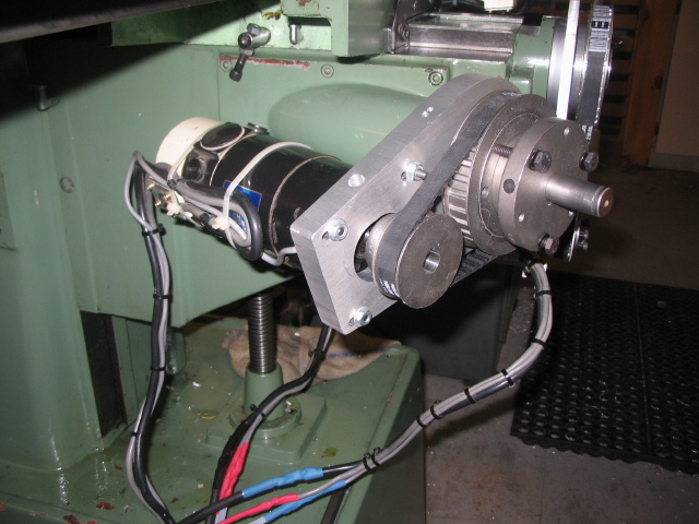
My servos looked like NEMA34 size, but while I was waiting for my steppers to arrive I had a closer look and found they were an odd size. The mounting screws were off just enough that drilling new holes would overlap the old. I had to make a complete new sset of brckets!
Oh well, having made one set I made the second set better, and took the time to add tapped holes for a belt cover.
I have experiemented with a couple controls for the PC. So far, I like the simple Xkeys pendant best. Actually, I would prefer a Genovation Keypad, as I used on my router, but when I went to order it the name X-keys stuck in my mind, so that what I ordered. The Genovation has an extra 4 keys, and is cheaper.
I have just started to use the machine- so far Ive just made a few test cuts. I will end this conversion page here, maybe do a page after I've had some experience with its use.