Spur Gear Differential
The origianl plan for MINNIE does not include a differential. Both rear
wheels are driven by a solid axle. I wanted to do a bit more, so I decided
to make a differential.
My first approach was to look at cutting some bevel gears. I studied the
information in Kozo Hirokas excellent book on Building the Climax, but
decided the gears would be more that I was ready to do. I was also
concerned that they would take up to much width, if made with a tooth
size large enough to handle the load.
I also looked at using the bevel gers from an old hand crank drill. I found
a couple identical drills, and am sure this would work, but again they
were to wide.
I finally settled on an all spur gear differential, based on one I saw
made by Fred Fox. Here is a photo of my differential.
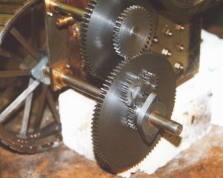 The operation of this arrangement as a differential may not be obvious. Ill try
to explain a bit. The large gear (bull gear, 90T) is driven from a pinion above it.
It is bushed and free to turn on its axle. On each side of the bull gear is a
wheel drive gear, 25T. The right wheelgear is directly connected to a flange
that drives the right wheel. The left wheel gear is keyed to the axle. It turns
through the main bearings and drives the left wheel.
The operation of this arrangement as a differential may not be obvious. Ill try
to explain a bit. The large gear (bull gear, 90T) is driven from a pinion above it.
It is bushed and free to turn on its axle. On each side of the bull gear is a
wheel drive gear, 25T. The right wheelgear is directly connected to a flange
that drives the right wheel. The left wheel gear is keyed to the axle. It turns
through the main bearings and drives the left wheel.
The differential action comes from the 3 gears mounted on the bull gear. On each
side, meshed with its corresponding wheel gear is a 20T Gear. On the side in the
photo this gear is seen directly above the wheel gear. It is held to the bull gear
by a short arbor, threaded into the bull gear. Just ahead of this gear, in mesh
with it, is a 14 T idler. This idler is pressed onto a shaft which is bushed
through the bull gear and carries the 20T gear from the left side.
Back to Minnie