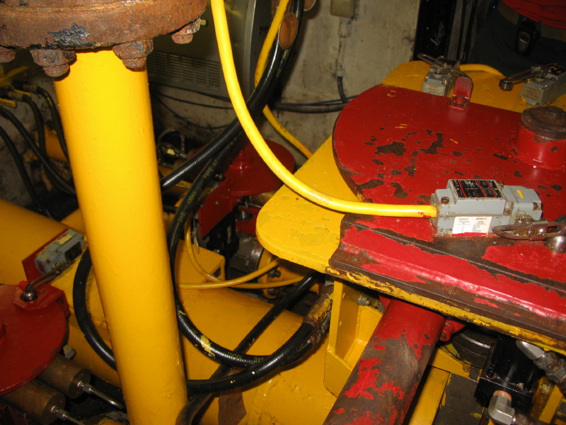
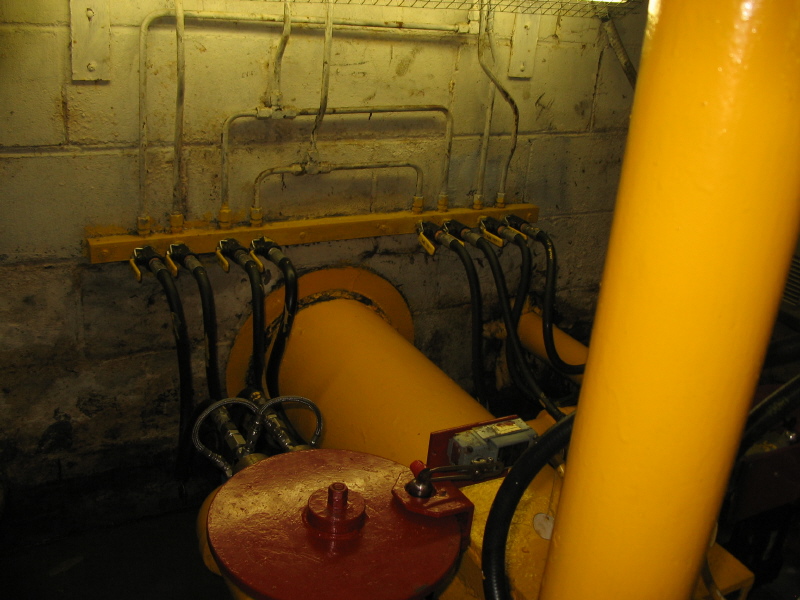
The yellow pipe coming down carries the makeup water form the electric pumps.
|
A closer look under the plates at the mounting brackets supporting the cylinder. |
|
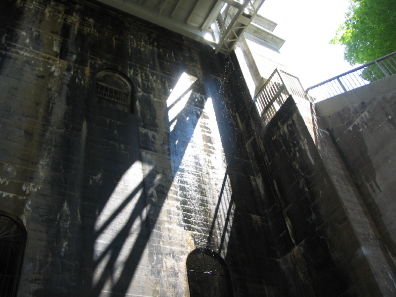
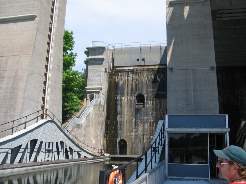
Standing below the chamber looking up at the joint between the chamber and the fixed lock wall. Surprisingly little leakage |
|
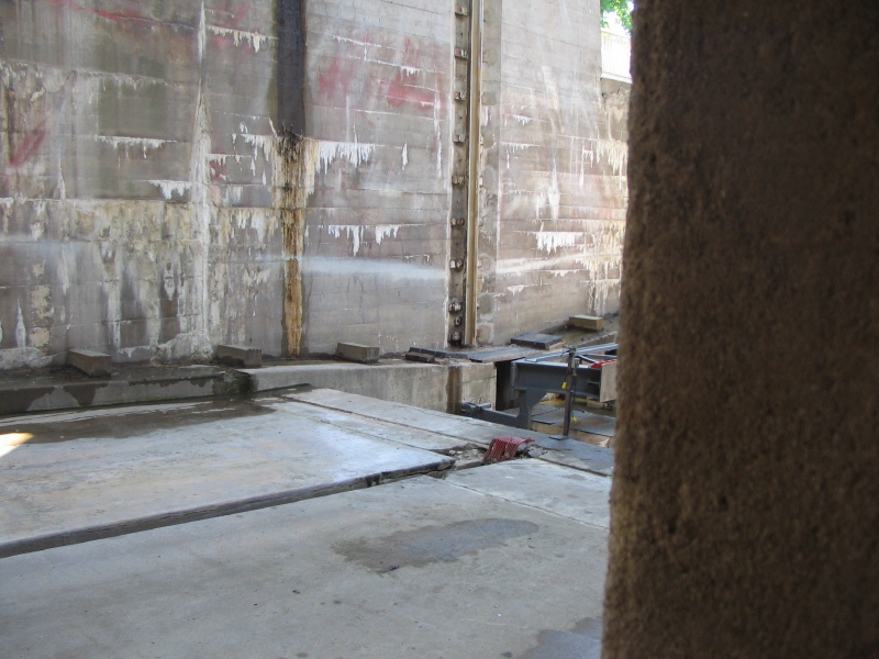
Looking back at the guide rails that keep the chamber aligned so it doesn't tip over. They look like rather light rails, but everything is perfectly balanced in that direction, and with water as a load you know its always distributed uniformly. |
|
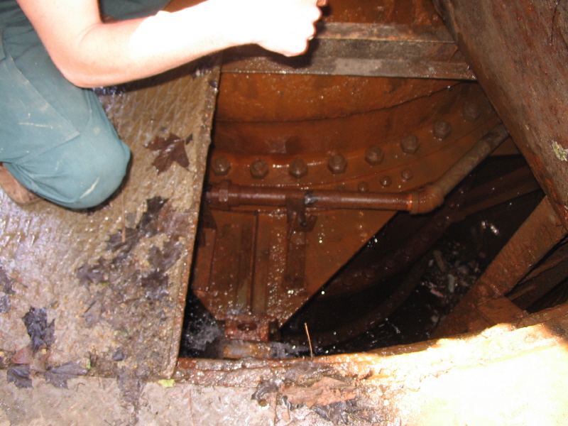
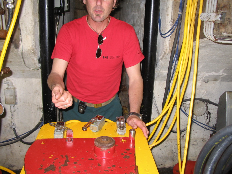
This is the main control valve, a butterfly valve operated by
hydraulic cylinders. Originally, until about 1965, it was operated from long
control rods down from the tower above. When it was switched to electro-hydraulic
control the control room was moved back to the main wall.
The yellow pipe coming down carries the makeup water form the electric pumps. |
|
The top of the valve showing the limit switches that signal when the valve is at the 10% and full open position. When operating they open the valve slowly, then close it slowly as it reaches the end of the trip to reduce shock loads. |
|
Here the main pipe exits through the wall to the ram. The smaller pipe is one of the control lines where water can be added or removed to trim the main system. |
|
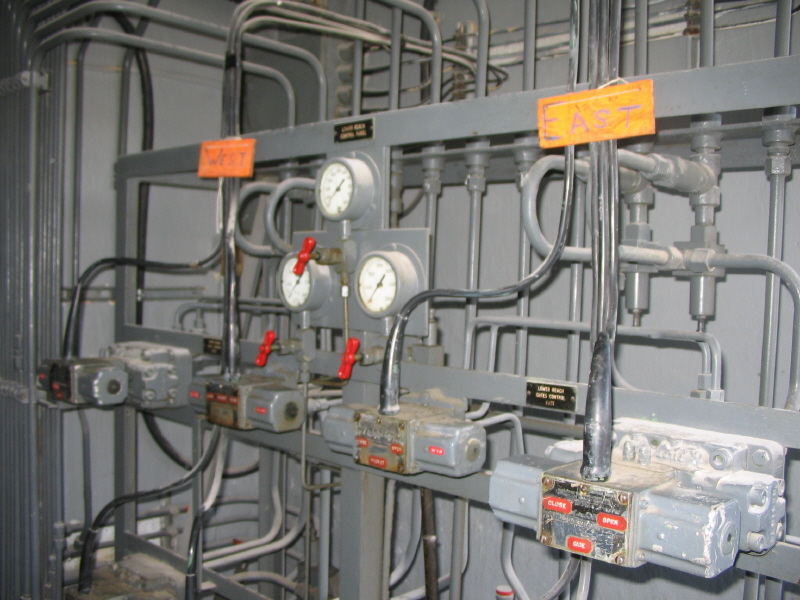
This is the electrical to hydraulic panel- electric lines from the control room operate these solenoids to control the hydraulic flow to operate both the transfer valve and the gate opening and latching. |
|
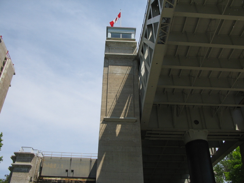
Back at ground level, between the locks, looking up toward the central tower that was the original main control tower. |
|
View of the main lock wall, with the water gate above, and the chamber down. |
Again my thanks to Ed Donald for a great tour.