At the CNC workshop in 2010 Keiling showed some new imported leadscrew that seemed much higher quality and for not much more money. If I were doing it over Id check that carefully, although I am still pleased with the McMaster Carr product.
One end of the lead screw will require a lot of machining to create a bearing shoulder and a thread to lock the bearing in position. Ive tried to machine this lead screw and it is VERY tough to do well, so my approach is to weld on a cylinder of a more machinable steel. After its welded I chuck the screw into a good collet and turn the extra cylinder as needed.
The right end of the leadscrew needs to be turned down below the root diameter of the screw so that the nut can be threaded on. This is hard, but its a simple turned diameter to a shoulder so its not bad. To make this end fit into the end blok a bronze flange bushing is made to fit the original screw and the turned end of the ball screw.
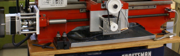
To mount the stepper motor I made a simple aluminum plate bored to fit the OD of the original bearing block. This is the surface on which part of the original gear train quadrant rides. I mounted the motor on simple stand-off legs and used a no backlash flex coupling between the stepper and the leadscrew.
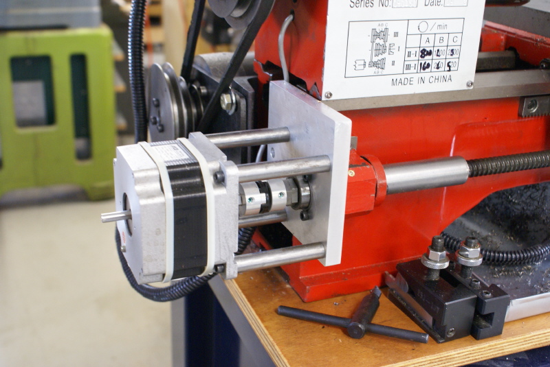
The photo shows the allen cap screws used to mount the plate to the bearing block, and the ball bearing. Normally this bearing would be pressed fully into a mount, but to keep this short I only pressed it in a shallow counterbore. The double nuts to apply end pressure to the bearings is also visable.
The original carriage is basically a cast iron box. I removed it and all its internal gears and half nuts. I then made two simple aluminum plates to bolt under the carriage slide. The end one is bored to fit the ball nut, which is placed inside the carriage box.
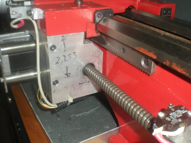
I left the rack gear on the lathe, although it is not needed, The photo shows the corner of the end plate had to be notched to miss the rack. It might have been cleaner to just remove the rack.