After considerable searching I found a re-print from MODEL ENGINEER on building MONA, an 0-6-2 Tank engine. The article is about a 3 1/4" gauge design, but it also details a 1 3/4" version. I actually had the article in my own library- I believe it must have come with a package of plans I bought a few years ago. This is a plan by LBSC that appeared in ME in 1954.
I got started just after I returned from my boat trip on the ICW, about Nov 16th, and have been working very steadily since then. I am determined to have it finished, at least runable, to take to Cabin Fever in January, 2006.
I began by cutting the side frame from .060" thick steel. The frame is about 12 1/2" long and 1 3/4" wide, with a complex contour and many holes. I drew the frame in TurboCAD and used Sheetcam to generate Gcode. I ran the parts on my Prazi mill
My first problem was the Prazi has only about 10" of working table travel, and the frame is just over 12" long. This required doing it in two sections.
I didnt take any photos, but I bolted a 3/4" thick aluminum plate to the mill table. I drilled 3/16" holes at the axle center positions, tapped the aluminum plate for 10-32 cap screws. I roughed out a blank for the frame, and drilled the three axle holes on my Clausing mill. My first operation was to drill all the holes in the frame for the various mounting brackets, cylinder block etc. Some of these holes were tapped 2-56 into the aluminum plate for extra hold down of the frames while dong the profile milling cuts.
I managed to scrap 5 parts before I got one good one, then did the next good one in a short time. The failures were caused by poor holding allowing the thin part to be lifted by the cutter, then by inaccurate layout of the rough blank.
|
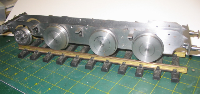
| This photo shows the frame assembled with the end beams and wheels and axles. Note that the driver wheels are simple steel discs, I plan to replace these with cast iron spoked wheels, but I wanted to get the model up on some wheels quickly so I could see what it was going to look like. |
|
| Another view of the assembled frame |
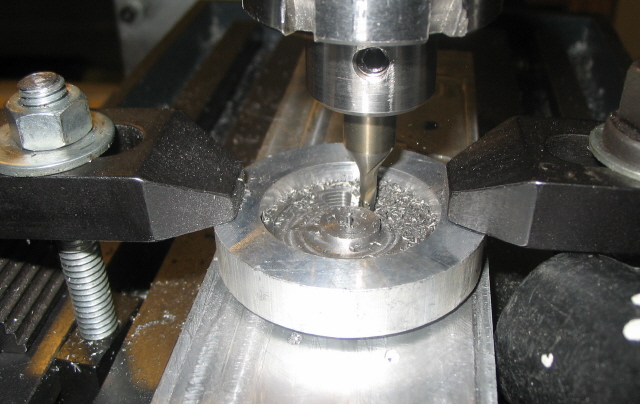 |
| To make the tender wheels I turned the blanks from durabar cast iron on my big Rockwell lathe. I finished the outside, including the flange on the lathe. I cut the spokes on my CNC mill. I used a 1/8" end mill and cut only .030 deep each pass, taking about 10 passes to get to the bottom. Altogether it took about 18 minutes per wheel. Note the wheel is clamped to an aluminum plate, and clamped down by an aluminum ring. |
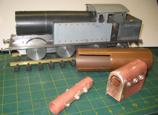 |
| Here is the flue tube and firebox after their soldering operations. Notice I've already built the steel shell for the simple boiler, which will also be scrapped. |
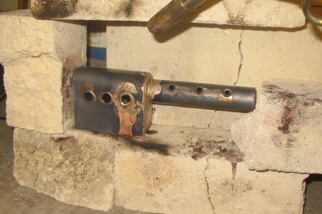 |
| This boiler required several successive silver solder operations. Here the flue and firebox are being joined. Note the stack of firebrick to contain the parts being soldered. |
As I went along I made some minor errors, and the cummulative effect was an ugly boiler with lots of sloppy silver solder. I trashed the whole thing and started over.